DAQ Electronics
CDT has equipped the detector products with adequate data acquisition electronics. These may be stand-alone or scalable multi-detector readout systems. In particular for POWTEX a robust, high data rate system comprising more than 300 client nodes has been designed (CDRS), which is currently being upgraded to provide a scalable DAQ system with modern FPGA hardware for ESS instruments such as DREAM and MAGIC.
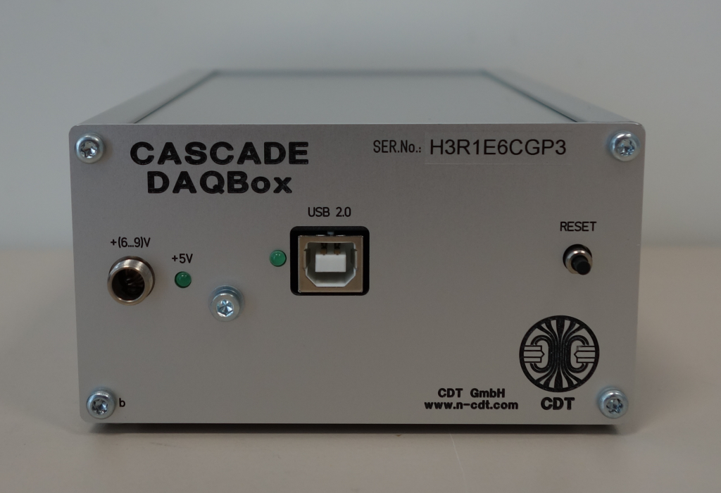
CASCADE DAQbox
CASCADE DAQbox is an FPGA based interface and processing device with a USB-data and control link to an operating PC that can be configured for detector readout and experimental control:
- Read out of up to two AS20 front-end devices operating the 64 channel readout ASIC CIPix 1.1 (maximum 128 channels).
- Interface to various NIM or TTL type digital signals, galvanically decoupled
- Allow for Multi-Channel-Scaling (pulse height analysis) on an analogue pulse input such as the AS20 diagnostic channel or the VV50 output.
4. Allow for continuous low noise current analysis at 700kHz sampling rate and 18 bit digital resolution with a low noise transimpedance amplifier board.
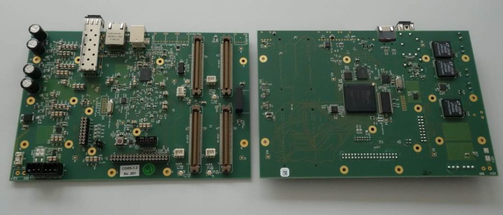
CDRS System
The CDRS System is the successor of the original CASCADE Detector Readout-System CDR, using a Xilinx Serial 6 Spartan device and can operate with up to four ASICs. Furthermore it can be accessed through USB or a SIS Gbit optical link interface. Several CDRS boards may be connected in a daisy chain to feed one receiving and controlling PCIe interfaced computing node. To all boards operate synchronously, a RJ45 socket is provided especially for the input of a master clock signal and synchronizing signals. CDT also offers special CDRS boards acting as clock master on which several RJ45 cables can be connected to other CDRS boards in a fan-out and star topology.
CDRE System
The CDRE System, employing the Xilinx Serial 7 Artix device, is envisioned to comply with ESS DAQ necessities and is equipped with a high performance jitter cleaning device that will allow the distribution and synchronization of a global time stamp to the CDRE devices in the field. CDRE will eventually comprise the interface to ESS supplied Assister Firmware on its FPGA while operating the CDT designed client detector. CDRE will transfer neutron event mode data indicating neutron events with location and time stamp.
CDRE may be populated for readout of up to eight AS20BS boards.